St9120u Wiring Diagram
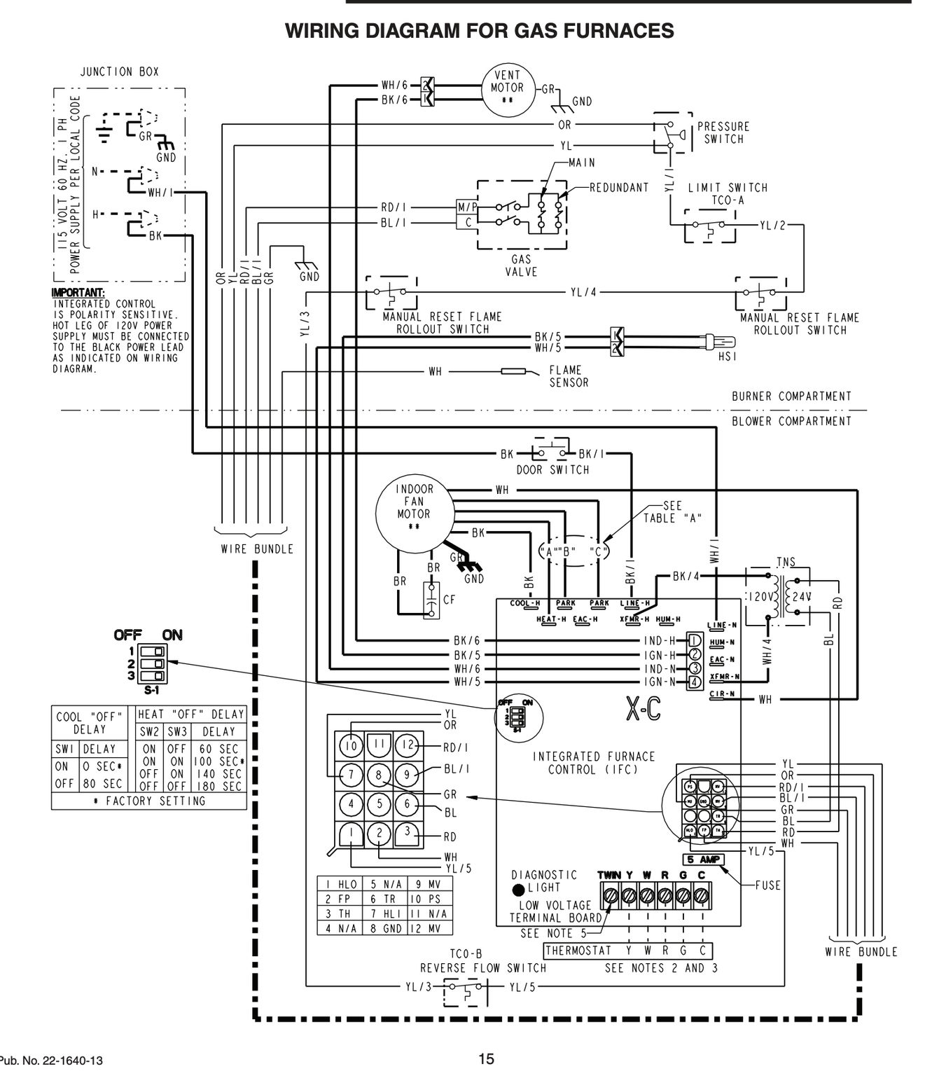
The gas valve is in the open position and nothing looks obviously wrong and the new control unit was hooked up according to the ST9120U wiring diagram. Arduino robot schematic pinout diagram robot control electronics schematic printed circuit board png.

Resideo St9120u Universal Electronic Fan Timers Installation Guide Manuals
Thanks for looking and good luck.

St9120u wiring diagram. The Timer should be mounted at a level where the display can be seen. SalesPromotional Materials-Sell Sheet for Y8427U S8610U ST9120U S9200U Q3200U Universal Service Kit Promotion Distributors English SalesPromotional Materials-Brochure for Mid-Atlantic Inventory Management Guide Residential Combustion English. Both C and TWIN wires shall lead in parallel to each other.
A wiring diagram is a simplified conventional pictorial depiction of an electrical circuit. When installing the ST9120U carefully check all appliance wires to make sure they are all connected to desired terminals at ST9120U. This type of switch is generally used in some home wiring systems and industrial applications.
A wiring diagram is a streamlined standard pictorial representation of an electric circuit. Honda cbr600 f3 cbr 600 electrical wiring harness diagram schematic 1995 1998 here. The heater gas control valve is a SV9500 Series.
We need a wire to wire cross-reference for the controllers because we are unable to access their tech support. S9200U1000 Universal Integrated Furnace Control Cross-Reference Guide Model Number Harness Field Settings Recommendation Safety Time Settings SW1 SW2 SW3 SW4 SW1 SW2. This is a brand new furnace can control circuit board.
Download Honeywell ST9100C Installation instructions. 3 pin toggle switch wiring. Its designed to replace all the Honeywell part s listed below.
Download honda cbr600 f3 1995 1998 service repair manual download. Wiring make sure that all wiring complies with local codes and. Honda cbr 600 f3 1995.
Diagram diagram treadmill dcmd57 control board wiring diagram full version hd quality wiring diagram. Proudly provides HVAC services to the North Georgia area includingAtlanta Canton Woodstock Marietta Cumming Alpharetta JasperFor mor. Dc treadmill motor controller.
After hitting the mounds running canyons or full out racing chances are your ride needs a little tlc to maintain. Disconnect power before making wiring connections. View and download honda cbr900rr service manual online.
And wiring may be used subject to any required electrical checks. Double Wall Switch Wiring Diagram This wiring diagram illustrates adding wiring for a light switch to control an existing wall outlet. Interior lights lincoln mark lt 2006 all wiring diagrams for power windows supplemental restraints pinouts ru radio system 05 08 fuse box diagram lock wire ls full 06 factory car pdf manual 1957 1965 04 f350 2008 over oem klx 650 of gmc sierra truck gm horn 4wd 2005 03 f150 st9120u.
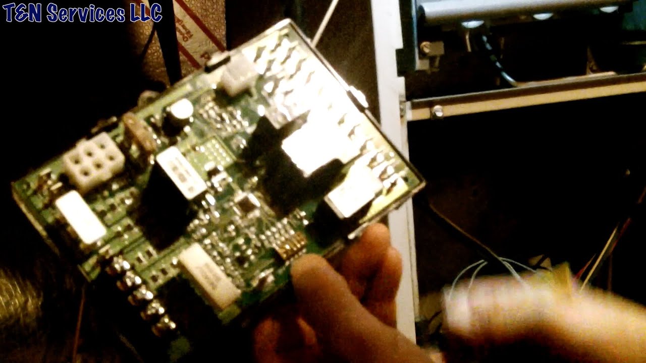
Also on the circuit board the led flashes so i know something isnt right. If the ST9100 is replacing an existing ST6100 then the existing wall-plate. The control board is the brain of your unit coordinating and executing the operation of other various components by sending voltage when.
A control board is constantly monitoring sensors and safety switches in the unit. Afc 1000 addressable fire panel wiring diagram type of circuit voltage type power type. Wiring a double switch.
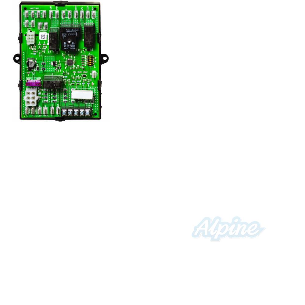
I am getting 26Volts from the transformerthe interior fan works in either AC mode or in fan on but now I dont have heater mode. 2 afc 1000 ins allation manal 5403649 re. This control is the central wiring point for most of the electrical components in the furnace.
Use insulate wires of wire gauge at least AWG 24 for the interconnections. Keep the wires out of wires under line voltage ignition cable and other sources of electrical noise. The furnace is a 1993 ICP.
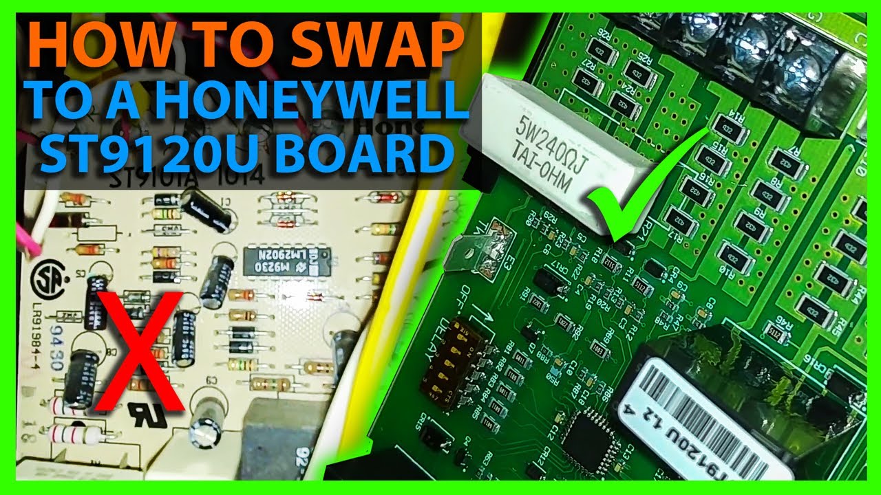
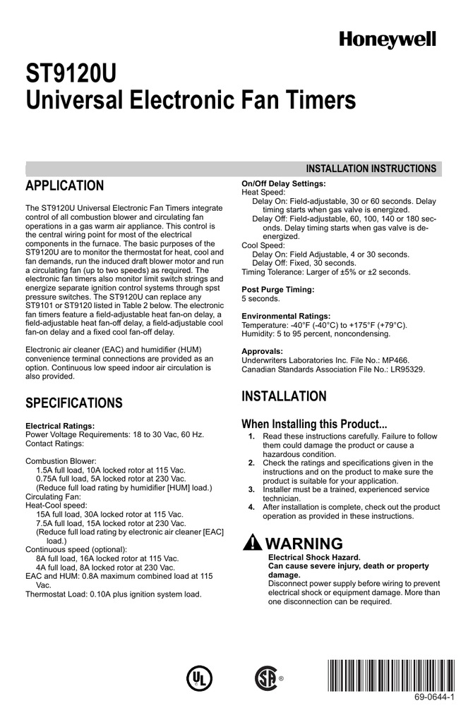
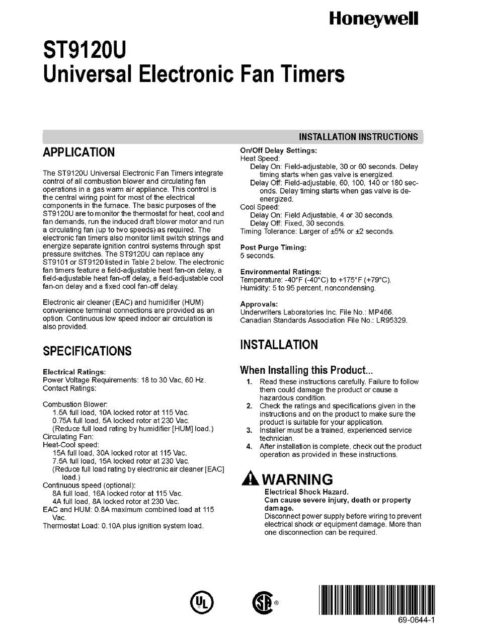
Turn off power to. Honeywell has replaced all their ST9120 series control boards with this universal control board kit which has wiring harnesess to be used with the furnace you are working on. The ST9120U Universal Electronic Fan Timers integrate control of all combustion blower and circulating fan operations in a gas warm air appliance.
2006 all carbureted softail dom. Honeywell Fan Control Board ST9120C 2002 ST9120C2002. Softail dash instrument wiring diagram.
Lf_3378 treadmill motor wiring diagram motor repalcement parts and diagram schematic wiring. 751c1 2008 Rocker C Wiring Diagram Wiring Resources 200 battery removal 320 switch removal 635 switch installation. The basic purposes of the ST9120U are to monitor the thermostat for heat cool and fan demands run the.
Rocker Switch Wiring Diagram Led Volt Dc Toggle More Diagrams Engine Light Bar Harness Kit For Trailer Lig In 2020 Basic Electrical Wiring Light Switch Wiring Switches Here is a diagram of a spdt toggle switch. Ok can someone help me with the wiring diagram from a st9120c 4057 to a st9120u. ST9120BU Wiring Conversion Instructions 1.
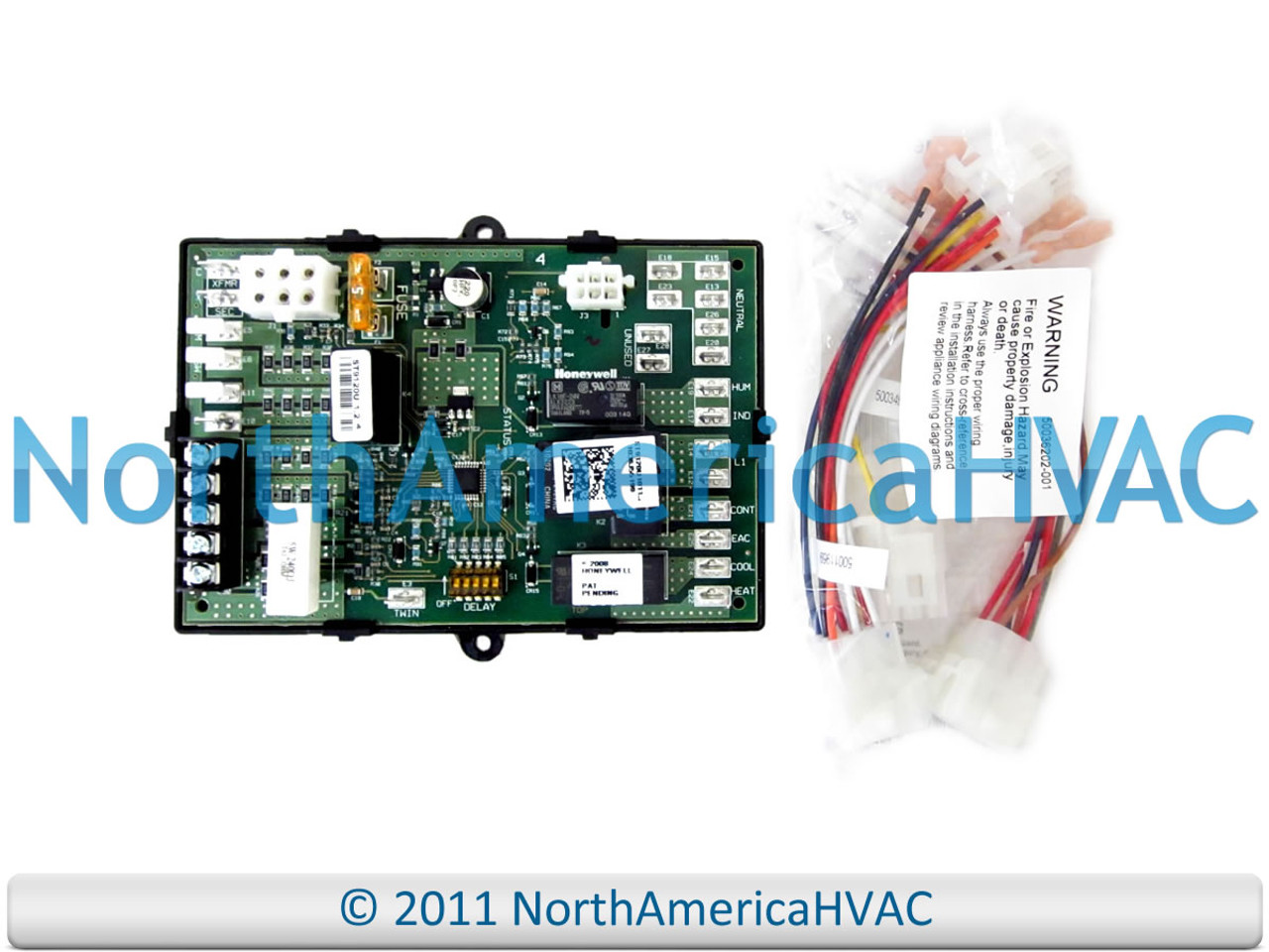
It is designed to replace the board part numbers listed below. Discussion starter 1 mar 19 2015. Mount the ST9120U Electronic Fan Timer in the appliance wiring compartment using the two 8 12-in.
None of their old ST9120 series boards are available so this kit is the only one you can use. It makes one of two connections. I need a wire for wire to where every wire go on new style.
Wire lengths shall not exceed 5 m 15 ft. Wiring CAUTION Explosion or fire hazard. Instructions included from Honeywell.
Nicet certified fire alarm systems the gamewell company is the oldest fire alarm company in the world. The control board is the brain of your unit coordinating and executing the operation of other various components by sending voltage when and where needed. Httpwwwoemhvacpartscanadacaproductshoneywell-st9120u1011-universal-control-boardhtmlHoneywell ST9120U1011 Universal Control BoardDescription.
Diagram 04 F350 Wiring Full Version Hd Quality Diagramland Andreapendibene It. Board comes with instructions and several wiring harnessness to convert old plug designs into this updated board. The wiring consists of two red wires one red loop one black wire and earth.
The wiring diagram provided by Honeywell does not address on which terminals the orange wires labeled 22 and 21 these leads went to the motor lead terminals on the original controller. Terminals 3 and 4 represent the toggle switch. You will only use one of wiring harnesses in the package if you require any of them- discard the rest.
Attached are the full set. When installing the st9120u carefully check all appliance wires to make sure they are all connected to desired terminals at st9120u. Incorrect wiring can lead to explosion hazard fire.
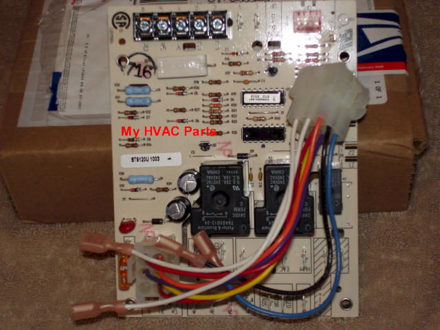
This is a BRAND NEW Honeywell Furnace Control Circuit Board.
How To Install The Honeywell St9120u Furnace Control Board Youtube

Diagram Honeywell St9120u1011 Wiring Diagram Full Version Hd Quality Wiring Diagram Soadiagram Prcsestosg It
Honeywell Universal Control Board St9120u1011 Replaces Obsolete St91201u1003

Resideo St9120u Universal Electronic Fan Timers Installation Guide Manuals

Resideo St9120u Universal Electronic Fan Timers Installation Guide Manuals

St9120u1003 Universal Electronic Fan Timer Training Module Ppt Video Online Download
Honeywell Furnace Control Circuit Board St9120u 1011 North America Hvac
Honeywell St9120u1011 Universal Electronic Fan Timer Replaces Honeywell St9120 St9101 St9141 And St9160 Models
Honeywell Fan Timer Install Youtube
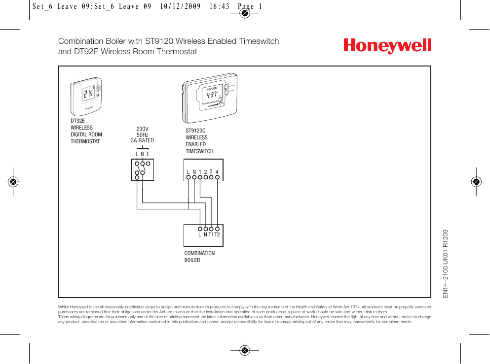
Faq Wiring Diagram Combination Boiler St9120 Manualzz
Wiring Diagram Of Old Furnace Board With A New Furnace Board

St9120u1003 Pdf Manualzz
Honeywell St9120u Manual Pdf Download Manualslib
St9120u1011 Overview Manualzz

Honeywell St9120u1011 Geary Pacific Supply
Fan Limit Switch Q A 5 Furnace Fan Limit Control Troubleshooting

Honeywell S9200 Universal Furnace Control Board Youtube

I Am Replacing A Havac Controller Where Do The S1 And S2 Wires Both Black On A St9120c 2002 Connect To On A

Honeywell St9120u1011 Universal Electronic Fan Timer Control