Rj45 Wiring Diagram
RJ45 wiring pinout for crossover and straight through LAN Ethernet network cables. RJ45 Wiring Diagram T568A Standard.

Apc Ups Cable Usb To Rj45 Electronic Circuit Projects Ethernet Wiring Electrical Circuit Diagram
It was introduced commercially in 1989 and became IEEE Standard 8023 in 1983.
Rj45 wiring diagram. THE complete Ethernet pinout cable wiring reference with wiring step-by-step guide. Now you have your Cat6 RJ45 Wiring you need to discover your electrical box. The most commonly used wiring standard for 100baseT is T-586B stanrard described above.
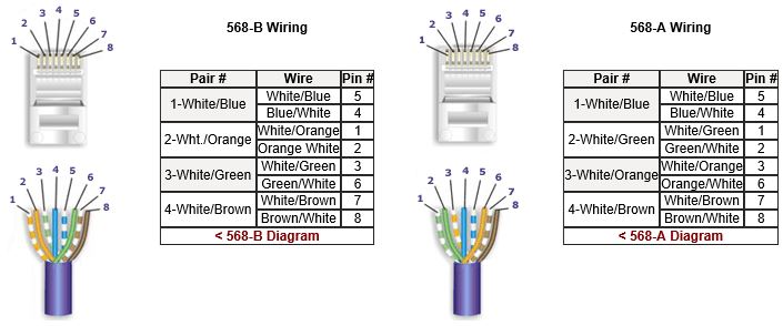
Rj45 colors wiring guide diagram tiaeia 568 ab. Remember the RJ45 wiring order. T568 a or t568 b wiring.
568a and 568b tiaeia color code diagrams and information. Eight wires are used as 4 pairs each representing positive and negative polarity. The typical rj 11 connector has six terminals.
A wiring diagram is a streamlined conventional pictorial depiction of an electric circuit. Attach the 3 wires of your Cat6 RJ45 Wiring to the matching receptacles to obtain your brand-new electric box. If not the arrangement will not function as it ought to be.
A good way of remembering how to wire a Crossover Ethernet cable is to wire one end using the T-568A standard and the other end using the T-568B standard. Wiring Diagram For Rj45 On Wiring Images. A wiring diagram is a streamlined standard photographic depiction of an electric circuit.
You can still use it with T568A pinouts but line 2 and 3 will be swapped. If your phone jacks pinouts follow USOC this adapter wont work. Eight wires are used as 4 pairs each representing positive and negative polarity.
Ethernet Cable Wiring Diagram Uk Fresh Cat 5 And Wire At Wiring Diagram Ethernet Cable Ethernet Wiring Ethernet Cable Cable Wire

Walnut Innovations Automatic Water Level Controller Water Level Sensors For Single Ph Submersibles Oper Submersible Pump Sump Pump Electrical Circuit Diagram