Greddy Tachometer Wiring Diagram
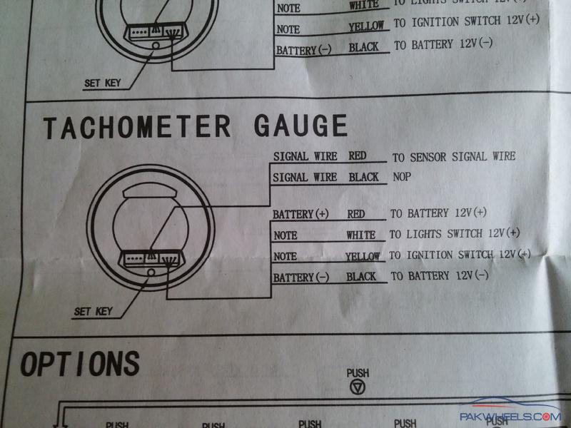
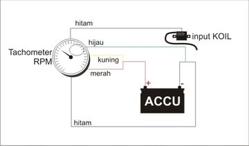
Please understand that proper wiring must be maintained throughout your vehicle. Digital Tachometer Wiring Diagram.
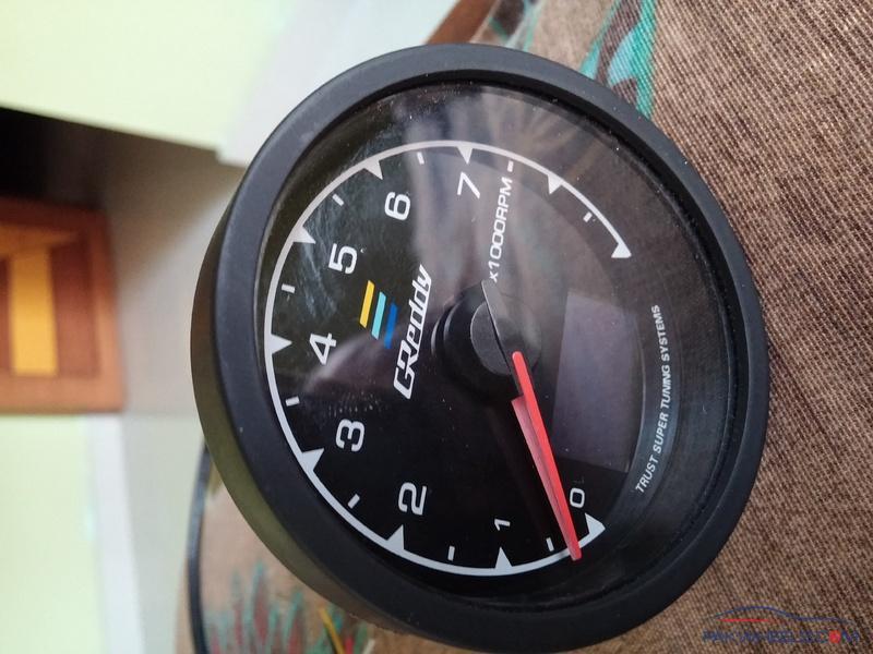
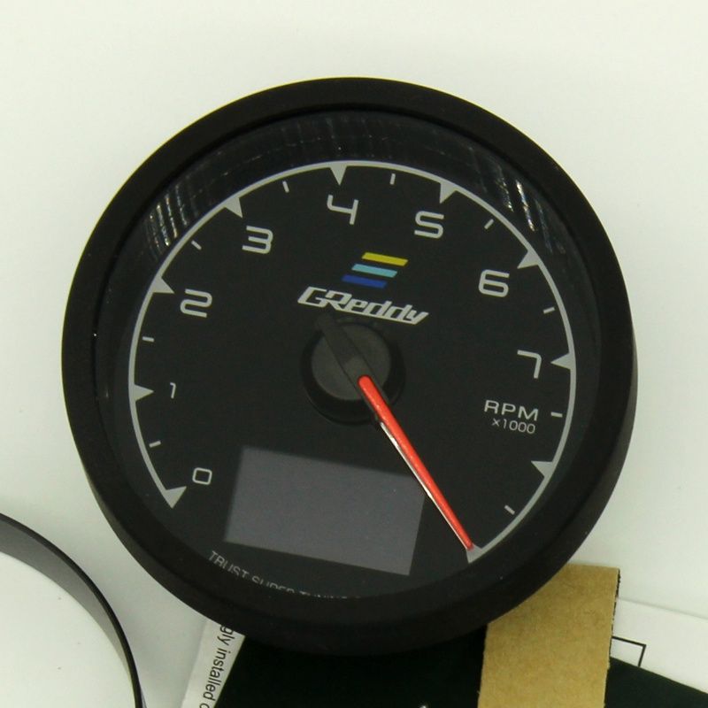
Want To Install Greddy Rpm Gauge In Vitz 2002 Vitz Yaris Pakwheels Forums
For GM HEI ignitions For aftermarket ignitions that provide a tach terminal or tach output wire.

Greddy tachometer wiring diagram. Connect the wire from the light switch to the remaining terminal on the lamp socket. Read and fully understand the wiring diagram before making any wire connection. Switch unit wire 45cm ft.
9 Vanderbilt Irvine CA 92618. It is intended to assist all of the average person in building a proper system. Trouble Shooting if your tach does not function properly after installation check the following.
A switched 12 or 24 volt wire can be found coming from the ignition switch. Apexi Super Afc 5 Button Knob Old School Instruction Manual Ecu Wiring. Connect the wire from the ignition coil as shown in Diagram D to the 2 terminal on t 6.
Please understand that proper wiring must be maintained throughout your vehicle. Apexi Super Itc 5 Button Knob Old School Instruction Manual Ecu Wiring. Are all electrical connections correct and tight.
Make sure all wires are long enough to reach the necessary positive and negative terminals and any wires from the sensor. The wiring diagram shown is a typical installation. If you own a 1UZ from 1990-1997 you really need to get this kit.
These instructions will be easy to comprehend and apply. Were not an auto parts supplier and I cant respond to inquries. Greddy Rpm Meter Wiring Diagram.
53 Best Of Autometer. ImageAuto Meter Of course this cheat sheet only covers the tachometers needle movement. Wiring Connect the tachometer wires as shown.
Wire the tachometer to the vehicle as shown in Diagram H on Page 4. 15 Connect the power supply tachometer signal wire to the connector on the back. Kbmd 240d Wiring Diagram Download.
The downstream side is the side leading to the engine. At this point the installation and wiring of your tachometer is complete. Merely connecting the tach output from the 1g ingiter to the tach input wire in the Miata harness produces no effect so Im guessing that the split to the ecu may in fact be necessary.
When the VDO Tachometer reading. Figure A Figure C Figure B For Distributor type ignitions with no aftermarket ignition box. I have a 1g wiring diagram and can read where everything goes but no explanation of why the tach signal splits.
Diagram E Proper wiring of the VDO Programmable Tachometer with typical ignition systems ˇˆ ˇ. A limited supply of the original best-selling Lextreme 1UZFE EGR Delete Kit is available for sale. Racetech 80mm rev counter race technology knowledge base 0 10000 with shift diagram led tachometer wiring rpm dmrr electronic sdometer gauge 95pk series 95mm 8000rpm voltmeter racing motor installation manual em 52mm historic 6 tacho question about mk1 water temperature 10 000 digital tachometers counters vehicle.
If it isnt the tachom-eter may pick up signals that have been produced by electri-cal devices other than the ignition system. Want to install greddy rpm gauge in vitz 2002 yaris pakwheels forums is back with their new multi d a gauges evolutionm mitsubishi lancer and evolution community lcd digital display meter tachometer 7 colours 2 in1 voltage 5 inch lazada ph sirus series colors 9 sho malaysia. Autometer Shift Light Wiring Diagram Unique Autometer C2.
Upstream would be the outboard side or closer to drivers fender Wire the Tach Adapters RED GREEN wire to the DOWNSTREAM side of the cut RedLight Green factory wire. Racetech Water Temperature Gauge Dmrr Racing Motor Parts. Wiring the Tachometer 1.
Following the diagram above wire the Tach Adapters RED wire to the UPSTREAM side of the cut RedLight Green factory wire. The tachometers in the diagram use a specific Auto Meter wiring color code so if youve got a different brand of tachometer you should reference its own schematic. Remove the key from the ignition and disconnect the negative terminal from the battery post.
A Japanese operation manual a wiring manual and a questionnaire card Quantity. This area is a growing library of the schematics wiring diagrams and technical photos. Do not install gauges into the passenger side or center of the dashboard.
Connect the wire from pin 4 to a switched 12 volt or 24 volt source. Dont coil up excess tachometer. Wire to a switched 12V source with an in line fuse.
356 Tach Wiring Wiring Diagram Tachometer Wiring Diagram. Wiring the Tachometer 2. Apexi Safcii 2 Ecu Wiring Diagrams English.
By Admin October 4 2018. Wire installations should be neat and tied down to prevent tugging and fraying of wires at connections. Autometer Tach Wiring Diagram For Readingrat Within Sport.
Continue reading 20022003 Toyota Tundra Greddy E-Management. Reconnect the negative batter you disconnected before beginning this installation. Prosport Gauges Peak Hold Warning Gaugesmm Peak recall gauges.
27112018 27112018 3 Comments on Greddy Peak Hold Warning Memory 60mm Gauge Wiring Diagram These are the new Halo series gauges from Prosport. Apexi Safcii 2 Ecu Wiring Diagrams Japanese. Unique Of Dixco Tach Wiring Diagram 06 Ford F Fuse Box 16 Gm Tach Wiring WIRING CENTER 13 Vintage Tachometer Wiring Diagrams 15 Dragon TachMay 19 The original Dixco 4 wire layout is Green Red White Black and the Mexican repro is Red Green White Black.
Autometer Pro Comp Memory Tach Wiring Anvelopesecondhand Net. Adjust the potentiometer on the back of the tach. Apexi Rsm Rev Speed Meter Round Button Wiring Instructions.
When connecting the connector push it in all the way until you hear them click in together. Defi Rpm Gauge Wiring Diagram. Sunpro Tachometer Wiring Diagram Wiring Diagram 4 Wire Tach Wiring Wiring Westach Cylinder Head Temperature Cht Gauge Ebay Westach Kod 3ct3 2 6volt 6 Cylinder Low Rev Tachometer The Stovebolt Forums Westach Cht Probe J Wire 18mm Ring 4 Lead 712 5wk From Aircraft Westach Egt Probe K Wire 1 5 8 2 5 Clamp 712 32dwk Non Tso From.
Wiring View and Schematics Diagram. Posted by Margaret Byrd Posted on March 23 2018. If there are any questions regarding this products please contact your GReddy Authorized Dealers or GReddy Performance Products Inc.
Wire the tachometer to the vehicle as shown in Diagram H on Page 4. Wiring Diagram arrives with a number of easy to follow Wiring Diagram Instructions. Follow this wire to a junction and attach the wire from pin.
Diagram F Fine adjustment of the VDO Tachometer when used with an alternator Compare the VDO Tachometer reading with that of a reference tachometer. Digital led rpm sdometer tachometer tachometers a complete guide rs circuit for bikes diagram mopar.
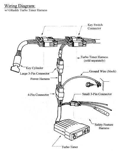
Greddy Turbo Timer Install

Cara Pasang Tachometer Indikator Defi Greddy Tutorial Youtube
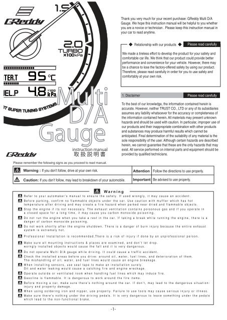
Multi D A Gauge Greddy

Greddy Sirius Meter Water Temp Obd Ii Set Pn 16001756
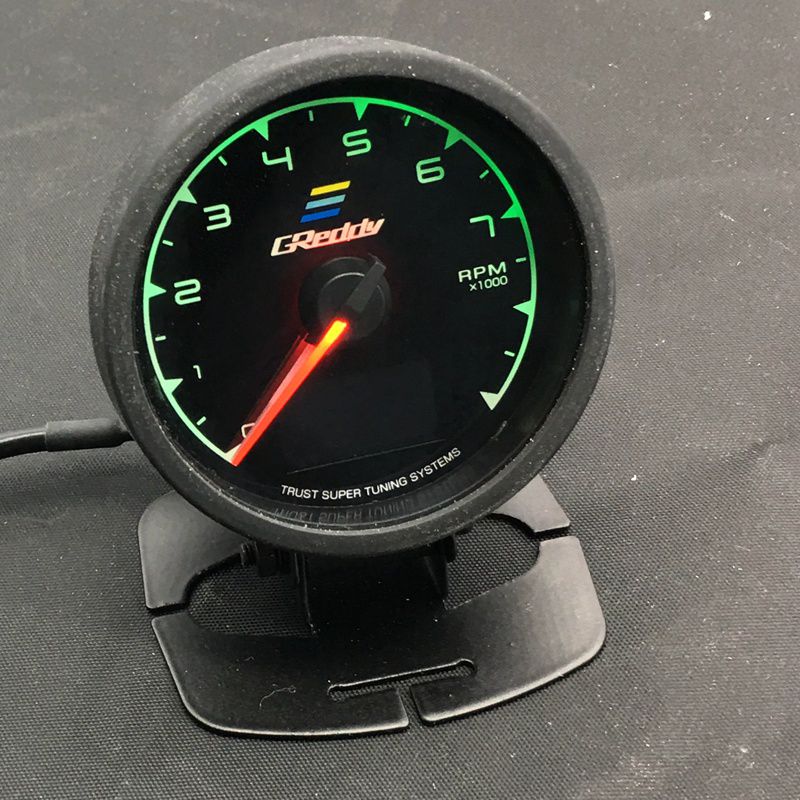
Buy Greddy Rpm Tachometer Gauge For Car Electrical Car Engine Speed Pointer Tachometer Tacho Gauge Meter Tester In Pakistan


Greddy Multi D A Boost Pressure Digital Gauge Not Working Youtube
Greddy Warinig Peak Hold Gauge Wiring Supra Forums

Shop Tachometer Online 62mm 2 5 Inch In 1 Racing Greddy Multi D A Lcd Digital Display Rpm Gauge Tachometer Sensor With As Cheap As 23 12 Piece Dhgate Com

Jual Greddy Tacho Rpm Gauge 7 Light Color Lcd Display 2 5 60mm Di Lapak Aprismobil Bukalapak
Shop Tachometer Online 62mm 2 5 Inch In 1 Racing Greddy Multi D A Lcd Digital Display Rpm Gauge Tachometer Sensor With As Cheap As 23 12 Piece Dhgate Com
Greddy Tachometer With Japakor Car Parts And Accessories


Greddy Volt Meter 10 Start Up Modes And Other Options Youtube
E Manage Ultimate Installation Manual Greddy
Want To Install Greddy Rpm Gauge In Vitz 2002 Vitz Yaris Pakwheels Forums

Greddy Tachometer Rpm 2inch Universal Tachometer Greddy Include Digital Rpm Dan Volt Meter Youtube
Greddy

Cara Pasang Indikator Tambahan Mobil Di Motor Keren Dan Fungsional Gridoto Com
Greddi Sirius Trust 74mm Auto Gauge 7 Colors Turbo Boost Volt Water Temp Oil Temp Oil Press Rpm Turbo Egt A F Ratio Fuel Gauge Boost Gauges Aliexpress

Want To Install Greddy Rpm Gauge In Vitz 2002 Vitz Yaris Pakwheels Forums