Defrost Timer Wiring Diagram
Here is a picture gallery about defrost clock wiring diagram complete with the description of the image please find the image you need. Wiring Diagram Freezer ½ to 2 HP Single Phase.
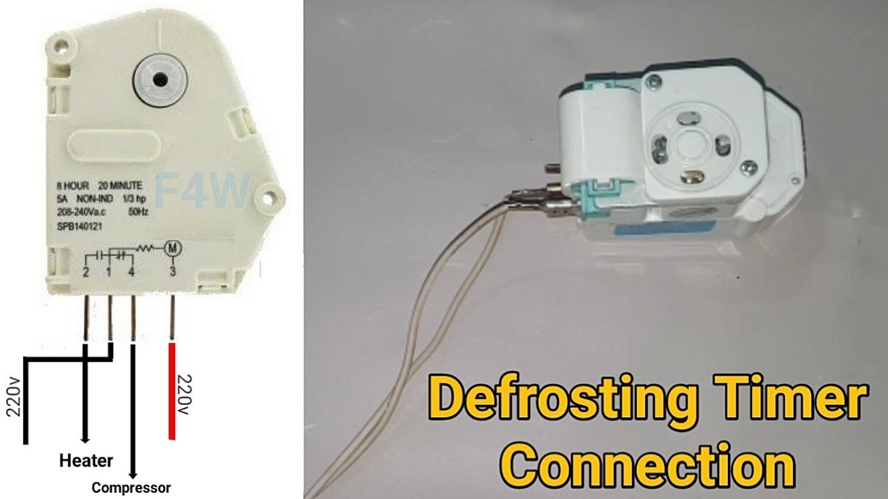
No Frost Refrigerator D Frosting Timer Function And Connection Fully4world Refrigeration And Air Conditioning Timer Hvac Air Conditioning

Refrigerator defrost timer wiring diagram A Beginner s Overview of Circuit Diagrams.

Defrost timer wiring diagram. Literally a circuit is the path that allows electricity to circulation. Precision Defrost Timer Wiring Diagram Fixed Frt045gm Defrost Timer Question Applianceblog Repair Forums. A wiring diagram is a simplified traditional photographic depiction of an electrical circuit.
Clip one probe of the VOM to each defrost timer -- not motor -- wire and turn the timer control. Whirlpool Defrost Timer Wiring Diagram Effectively read a electrical wiring diagram one offers to know how the particular components within the system operate. Terminal 1gain power from the blue line through the defrost heater while terminal 3 connected to terminal 4 to compressorwhen the terminal 3 connected to terminal 2 in defrost mode timer will stop until the bimetal cut outmost refrigerator japan made use this kind of wiring diagram.
Defrost timer wiring diagram freezer to paragonable beauteous and. Whirlpool Refrigerator Defrost Timer Wiring Diagram russellreichert August 13 2021 Templates No Comments 21 posts related to. Whirlpool W Refrigerator Defrost Timer Now you can do as the instructions suggest and find the wiring diagram from your fridge to determine if youre Option A B or C.
Timer only advances when the compressor is running. Lg Gr 242 Service Manual View Online Or Repair. Series Defrost Timers Retail store display freezers and reach-in coolers Typical line voltage wiring diagram.
For instance in case a module will be powered up and it sends out a signal of half the voltage and the technician does not know this hed think he provides an issue as he would expect a new 12V signal. You will need to be able to read a wiring diagram but I found this situation to be simply a matter of matching examples of pictures line diagrams515. Honestly we have been realized that 8145 20 wiring diagram is being one of the most popular field at this time.
Defrost time controls hvac r grasslin dtmv40 series operating t 49f wiring diagram swapping timer on paragon 8145 20 25 commercial intermatic dtav40 installation required snaps into existing enclosures auto multi voltage 40 the for true part 831993 tork clock owner s manual bypass basic control dcne timers 8000 whirlpool or temperatu re 120 supply 365 instructions. Wiring diagram walk in freezer defrost timer wiring diagram heatcraft walk in freezer wiring diagram download building wiring layouts show the approximate locations and also interconnections of. Commercial Defrost Timer Wiring Diagram Paragon Defrost Timer regarding Defrost Clock Wiring Diagram image size 476 X 332 px and to view image details please click the image.
Even the cumulative defrost systems fail to account for the number of times the door is opened. The Paragon defrost and the Tork electric timers offer versatility and unbeatable quality to. A very first look at a circuit diagram may be confusing however if you can check out a train map you can review schematics.
Wiring Diagram Freezer ½ to 2 HP Single Phase. Paragon Defrost Timer 8145 20 Wiring Diagram Wiring Diagram within 8145 20 Wiring Diagram image size 476 X 332 px. Lg Defrost Timer Wiring Diagram.
The function is the same. The defrost timer is operated by a single-phase synchronous motor like those used to operate electric wall clocks Figure 281. Explains the working of the defrost timer defrost heater and defrost limit thermostat aka.
Ge Defrost Timer Wiring Diagram wiring diagram is a simplified welcome pictorial representation of an electrical circuit. By Margaret Byrd June 28 2021. In a common wiring diagram for a time-initiated temperature-terminated Normally closed contacts of the defrost timer are wired in series.
Paragon sell sheet shows model numbers and wirings diagrams Replace with TT or CT series. Collection of paragon defrost timer 8145 20 wiring diagram. Applications and Wiring Diagrams MECHANICAL DEFROST TIMER 8000 Series Customer Service Telephone 18003046563 Customer Service Facsimile 18004260804.
A schematic drawing of the timer is shown in Figure 282. Typical wiring for defrost on a single evaporator freezer - YouTube. After the timer measures an accumulated run time equal to a predetermined amount the system will enter into the defrost cycle.
This type of defrost is often referred to as a cumulative run-time defrost. Refrigerator defrost timer wiring diagram. In this video you can learn about the defrost timer wiring diagram of a frost free refrigerator and circuit.
OUTDOOR WALK-IN COOLERS AND FREEZERS. The Paragon Series Auto Voltage Defrost Timer is designed competitive voltage-specific mechanical defrost timers eliminating Wiring Diagrams. The contacts are operated by a cam that is gear driven by the clock motor.
Test the defrost timer with a VOM set to the RX1 scale. Getting from factor A to point B. Do not set a cooler thermostat below the walk-ins design temperature or product Diagram 9 - Typical Wiring Diagram for Single with Defrost Timer OnlyJul 02 I can increase the defrost time Grasslin timer but dont believe it will be the best solution.
The brain of the frost free appliance is the defrost timer. Typical wiring for defrost on a single evaporator freezer. Lg gr 242 service manual view online timer in frost free refrigerator 462cvf t582gv single door inverter t382sv 392cvf samsung defrost for whirlpool electrical wiring.
The defrost timer has four pins labeled from 1 to 4. It shows the components of the circuit as simplified shapes and the knack and signal connections amongst the devices. It reveals the elements of the circuit as streamlined shapes and also the power as well as signal links in between the tools.
Defrost limit switch or limiter in a modern frost free refrigerator or freezer. Set the correct time of day on the defrost timer.
Pin By Ram Has On Air Conditioner Refrigeration And Air Conditioning Air Conditioner Maintenance Air Conditioning System

Unique Walk In Freezer Defrost Timer Wiring Diagram Diagram Walk In Freezer Whirlpool Refrigerator

Pin On Electricity

Description The Non Frost Refrigerator Diagram Is Very Easy It Has Red Wire Phase And Blue Wire Neutral Refrigeration And Air Conditioning Frost Refrigerator

Collection Of Freezer Defrost Timer Wiring Diagram Wiring Diagram At For Walk In Freezer Diagram Timer

Samsung Fridge Compressor Wiring Diagram Refrigeration Diagrams Refrigerator Com Full Size Of Single Diagram Electrical Circuit Diagram Basic Electrical Wiring

Domestic Refrigerator Wiring Electrical Wiring Diagram Refrigeration And Air Conditioning Circuit Diagram

Necesito Un Diagrama Electrico De Una Nevera In 2021 Electrical Installation Electricity Power

Double Door Fridge Wiring Diagram Doubledoorfridgewiringdiagram In 2021 Refrigeration And Air Conditioning Double Door Fridge Hvac Air Conditioning

Domestic Refrigerator Wiring Electrical Wiring Diagram Refrigeration And Air Conditioning Circuit Diagram

Room Air Cooler Wiring Diagram 1 Room Air Cooler Wiring Diagram 1 Note Check The Room Air Cooler Wiring Diagram Ge Refrigerator Room Air Cooler Air Cooler

Refrigerator Defrost Timer Wiring Diagram Diagram Door Switch Timer

Westinghouse Refrigerator Defrost Timer 215846602 5300187484 By White Westinghouse 9 43 Frigidaire Westinghouse Oem Westinghouse Large Appliances Frigidaire

Citra Pelangi Nusantara Kelistrikan Kulkas Refrigerator Electrical Listrik Kulkas Saluran Udara

4qtv V35ud27lm

Citra Pelangi Nusantara Kelistrikan Kulkas Refrigerator Electrical In 2021 Kompresor Listrik Saluran Udara
30 Unique Refrigerator Start Relay Wiring Diagram A Control Relay Is Used In The Automotive Industry To Restrict An Air Conditioner Maintenance Relay Diagram

Freezer Defrost Timer Wiring Diagra Diagram Wire Timer

Pin On Refrigeracion Y Aire Acondicionado